Optical Transfer
The ability of a lens or optical system to pass information -- which as far as we're concerned here means to form an image -- can be characterised in
spatial terms by its
Point Spread Function, or in
frequency terms by its
Optical Transfer Function. The PSF tells you the shape of blurry smudge you'll get in the image plane if you place a single point source somewhere in the object plane; the OTF tells you the response of the lens to a given spatial frequency. The OTF is conventionally expressed as the normalised Fourier transform of the PSF, where normalisation in this case means scaling so that the value at the zero frequency is 1. The two are to all intents and purposes equivalent, so which one uses depends on which is more convenient at the time; often, as today, that's the OTF, even though it's in some ways less intuitive.
For an idealised circular lens -- ie, one without aberrations -- the OTF is a fairly simple function of frequency that looks like this:
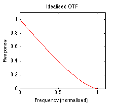
There's a perfect response for the zero frequency -- which is basically the average brightness ever the whole image area -- declining almost linearly
1 to the
cut-off frequency. The latter is a hard limit on resolvable detail and is given by:

where
λ is the wavelength of light being used to form the image, and
NA is the
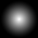
numerical aperture, a measure of the spread of light from the object that the lens is able to capture. Our idealised transfer function corresponds to a frequency mask that looks like this:
We can use such an OTF to simulate, in a somewhat optimistic fashion, the business of structured illumination microscopy.
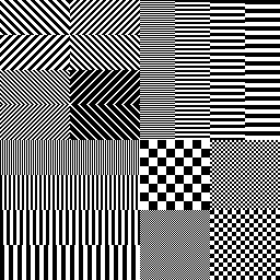
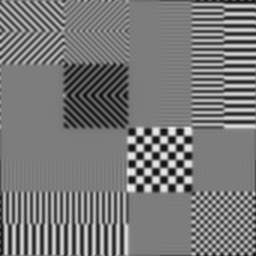
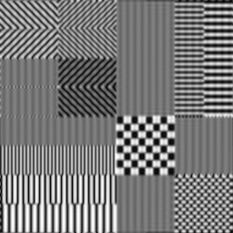
Let's begin with an image that represents our object as it really is, ie with no intervening optical processes to muck things up. This image has been chosen to have lots of really annoying high frequency components:
We're not going to spend much time in the frequency domain here, but just for your amusement here's a quasi-representation of what this image looks like after a Fourier transform:
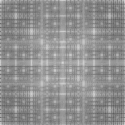
Busy, isn't it? Notice how much detail there is all the way to the edges. When we apply the OTF, we're going to throw away a whole lot of that -- imagine plonking the earlier circular mask image (which is to the same scale) in the middle of this frequency map, tossing out everything that's outside the mask or covered by black, and muting the stuff covered by grey. Only the white centre gets through unscathed.
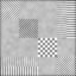
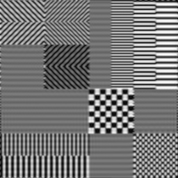
The result, back in the spatial domain, gives us an idea of what we'd see through a lens with a cut-off frequency lower than some of the frequencies in the target:
As you can see, the resulting image is noticeably blurred and a fair bit of detail is gone: the finest lines and checks are now a uniform grey, while the next size up have lost much of their contrast and are only dimly visible.
So far, we've assumed that our object is all alone on the far side of the lens, with nothing else going on to muddy the waters. This is typically not the case in fluorescence microscopy, where there may be all manner of crap busily fluorescing in the out of focus regions. That light is also picked up by the lens, so the image might actually look more like this:
Our goals for structured illumination are two-fold. First, we'd like to get rid of as much of the extraneous out of focus mush as we can; second, we'd ideally like to sharpen up the lateral detail too. The latter is a trickier task, and we're not going to go all that far with it today, although we can gesture in that direction; but we should be able to make some decent progress with the former.
The mechanism for this, as described
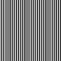
previously, is to add a pattern to the excitation light with which we're illuminating the sample. For simplicity, we'll use a simple sine grating, which looks like this:

Unfortunately, we can't just magically create this out of nowhere: it has to be projected onto the sample through some lens system, which will almost always include at least the objective lens of the microscope we're viewing with. In the course of this projection, the pattern will undergo some degradation of its own. If we assume that the OTF for this is the same -- not, in general, a safe assumption, but adequate as a first approximation -- then by the time it hits the target it's going to look more like this:
After which it still has to go back through the system to form an image, so even in the absence of noise the best we can hope for from the grating itself will be something like this:

This blurring somewhat diminishes the grating's power to improve resolution, but what can you do? In any case, if we take three separate exposures of our grating, shifting it along a bit in between each one, applying the OTF on the way in, lighting up the target accordingly, adding out of focus noise and then running the whole lot through the OTF again, we'll wind up with something like these frames, which I've combined into an animation because it's more fun that way:
Now, you might reasonably complain that this doesn't seem like much of an improvement; and it's true it's a bit of a bloody mess. However, there are a couple of interesting things to note about this sequence, and these will be key to recovering something better.
For one thing, what we appear to see isn't all the same from frame to frame; the effect is most noticeable in the lower left area. It's caused by the illumination frequency interacting with the sample frequencies; we'll come back to this shortly.
For another, although it isn't so obvious, the out of focus fluorescence doesn't change much from frame to frame, while the in-focus image changes a lot. The reason for this is that the illumination pattern is itself out of focus away from the object plane, blurred into a uniform grey pretty much regardless of position.
2 We can use this difference in behaviour to basically remove the unchanging field altogether, using a calculation like this:
 I1
I1,
I2 and
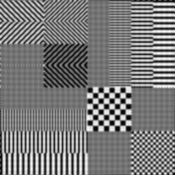
I3 are the three constituent images. Here's the result of performing that calculation with the frames above:
While this image is far from perfect, it certainly compares favourably to the earlier fogged-out single exposure, with virtually all of the extraneous clouding eliminated.
Furthermore, if you compare the vertical bars in the lower left to their counterparts in the unfogged blurred image above, you can see that the resolution there is noticeably improved. This is due to the interactions with the grating frequency mentioned earlier. These moiré fringing effects allow for more detail information to sneak through the OTF by shifting it to a lower frequency. The same improvement does not occur with the horizontal bars in the upper right, because they are perpendicular to the grating and thus unaffected by its periodicity.
We could also take a set of exposures with a
horizontal grating, and combine those in exactly the same way to get an image in which the horizontal bars are improved instead of the vertical:
In both these images there is obvious
banding in the direction of the grating, which is especially noticeable in the low-detail regions. This is due to insufficient separation between the different phases, which is in turn due to the OTF blurring the illumination pattern -- if the pattern were perfectly transmitted there would be no banding. It may be possible to reduce this by using a different pattern more optimised for the OTF, and this is one of the things I'm investigating at the moment.
The one-dimensional improvements in lateral resolution seen above are all very well, but really we'd like to sharpen things up across the whole plane. There are a number of more sophisticated techniques we might apply to this problem, and those are something else I'm currently working on. But it turns out that even the single easiest, most inexpensive and, frankly,
lamest approach does still net some benefits over the raw image:
All that we've done here is to add the two images together, which basically averages the better areas from each into the weak areas of the other. This has two obvious drawbacks: the improvements are watered down, and we pile on both sets of banding artefacts into a nasty
gingham effect.
Still, in some biological applications this might be a price worth paying -- being better able to resolve small objects in a mostly black (and thus band-free) field, for instance. And I'm reasonably optimistic that we can do better than this with some less stupid processing.
Watch this space...
1 But not quite. In fact, the response is proportional to the area of overlap between two copies of the lens pupil separated by an amount representing the frequency; in this case the pupil is circular, which makes the response function simple. At the cut-off frequency and beyond, there is no overlap and thus those frequencies are not transmitted. Alas, this interpretation doesn't hold in the presence of aberrations, which have the effect of distorting the response mapping in unfavourable ways.
2 This is terribly simplified in this simulation, since we don't model the whole 3d space and consider the degree of defocus, but the general idea should hold true. The actual thickness of the in focus section depends on the frequency of the illumination pattern: the finer the pattern, the tighter the section. Obviously this has to be balanced against the OTF resolution limit, since as the pattern approaches this it becomes more and more indistinct and conveys less and less information.
Posted by matt at July 5, 2007 03:15 PM